运动学
运动学是几何学在各种机器人机构控制中的应用。运动学方程通过提供特定的输入来控制机械装置,以实现所需的输出。
这里的许多运动学方程式取自 FIRST 机器人竞赛中的控制工程(书籍) 和 FTC 移动机器人运动学(论文) ,其中包含相关推导。虽然这里只显示了坦克(差速驱动)和机械臂运动学方程,但这些资料还包含其他机构的推导,如转向和惰轮里程计。
正向运动学与逆向运动学
机械装置的正向和逆向运动学可能有不同的方程组。正向运动学是根据系统的输出状态来确定系统状态的方程,而逆向运动学则是根据所需的状态来确定系统的输出。例如,在动力传动系统中,正向运动学将根据车轮的单个速度确定机器人的车身速度,而逆向运动学将根据所需的车身速度确定所需的车轮速度。
坦克底盘(差动驱动)
坦克或差速驱动是一种传动系统,由机器人两侧独立驱动的两组车轮组成。更多详情请参见 坦克(滑移装载机)传动系统 部分。
变量
本节使用以下变量。
\(v_r\) 表示右轮的线速度
\(v_l\) 表示左轮的线速度
\(v_f\) 表示机器人相对于自身的前进速度
\(\omega\) 表示机器人的旋转速度,单位为弧度/秒
\(r_b\) 表示基本轨道半径,或车轮与机器人中心之间的距离(车轮间距的一半)。
警告
除了 \(\omega\) 之外,这些变量代表的是 线性 速度,而不是 旋转 速度。以弧度/秒为单位的车轮旋转速度可以通过乘以车轮半径转换为线速度。
正的旋转速度(\(\omega\))将使机器人从上方看时顺时针旋转。
正向运动学
坦克驱动装置的前进运动学将车轮的速度与机器人相对于自身的前进速度和旋转速度联系起来。前进速度 \(v_f\) 和旋转速度 \(v_{\theta}\) 为:
反向运动学
坦克驱动装置的逆运动学将机器人的期望速度与车轮所需的速度联系起来。这些速度如下:
麦克纳姆轮底盘
变量
麦克纳姆底盘的运动学使用的变量与差分驱动相同,但有四个车轮速度变量和一个额外的机器人速度矢量(从左到右的速度)。
\(v_\mathrm{fr}\) 表示右前轮的线速度
\(v_\mathrm{br}\) 表示右后轮的线速度
\(v_\mathrm{fl}\) 表示左前轮的线速度
\(v_\mathrm{bl}\) 表示左后轮的线速度
\(v_f\) 表示机器人相对于自身的前进速度。
\(v_s\) 表示机器人相对于自身的横移(侧移)速度。
\(\omega\) 表示机器人的旋转速度,单位为弧度/秒
\(r_b\) 表示基本轨道半径,或车轮与机器人中心之间的距离(车轮间距离的一半)。
警告
除了 \(\omega\) 之外,这些变量代表的是 线性 速度,而不是 旋转 速度。以弧度/秒为单位的车轮旋转速度可以通过乘以车轮半径转换为线速度。
正的旋转速度(\(\omega\))将使机器人从上方看时顺时针旋转。
正向运动学
麦克纳姆轮底盘的正向运动学将车轮的速度与机器人相对于自身的前向、侧移和旋转速度联系起来。这些是:
反向运动学
麦克纳姆轮底盘的逆运动学将机器人的期望速度与车轮所需的速度联系起来。具体如下
Manipulators
Gravity Compensation
Often in FTC, teams have arms that swing out around an axis. Controlling these arms requires a bit of thought as depending on the angle they’re at, the effect of gravity drastically changes.
Our first step is defining a reference frame. Our recommendation is to define zero as straight to the side, as this is when gravity has the greatest effect on your arm. Other reference frames will still work, but the exact trigonometry will change.
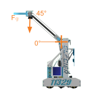
11329 I.C.E. Robotics
In a reference frame like this, the relative force of gravity will be equal to the cos of the angle. This makes sense as when the cos function is evaluated at zero degrees, it returns 1, while at 90 degrees where there is no effect of gravity, it returns 0.
Assuming you have an encoder on your arm, you can find \(\theta\) (the angle of the arm relative to the vertical) using something similar to the following pseudocode.
备注
DEGREE_PER_TICK can be found by taking 360 divided by your encoder resolution all multiplied by your gear ratio. For example, for a 19.2:1 goBILDA Yellow Jacket, there are 537.7 ticks per revolution, and so \(\frac{360}{537.7}\) degrees per tick at the gearbox output shaft. If there was a 2:1 gear ratio after that, then the ticks per revolution would instead be \(\frac{360}{2 \times 537.7}\)
current_angle = (TICKS_AT_ZERO - current_tick) * DEGREE_PER_TICK
The typical way to utilize the effect of gravity you just found, is to pass it in as a feedforward parameter to a PID controller. We cover this in Gravity Compensated Feedforward.