Control System Electronics
This page contains a breakdown of known electronics in the REV Robotics control system, as well as notes regarding them.
Expansion Hub Internals
Warning
Don’t take apart a Control or Expansion Hub unless you really know what you are doing. They can be damaged in the process, especially if one does not know how to properly reassemble it.
Lynx Board
“Lynx” is the codename of the board within the Expansion Hub and Control Hub that interacts with hardware. References to “Lynx” made in the FTC® SDK refer to this board. It appears to have been developed by both REV Robotics and DEKA (Dean Kamen’s company). A reverse-engineered schematic can be found here.
Warning
Don’t take apart a Control or Expansion Hub unless you really know what you are doing. They can be damaged in the process, especially if one does not know how to properly reassemble it.
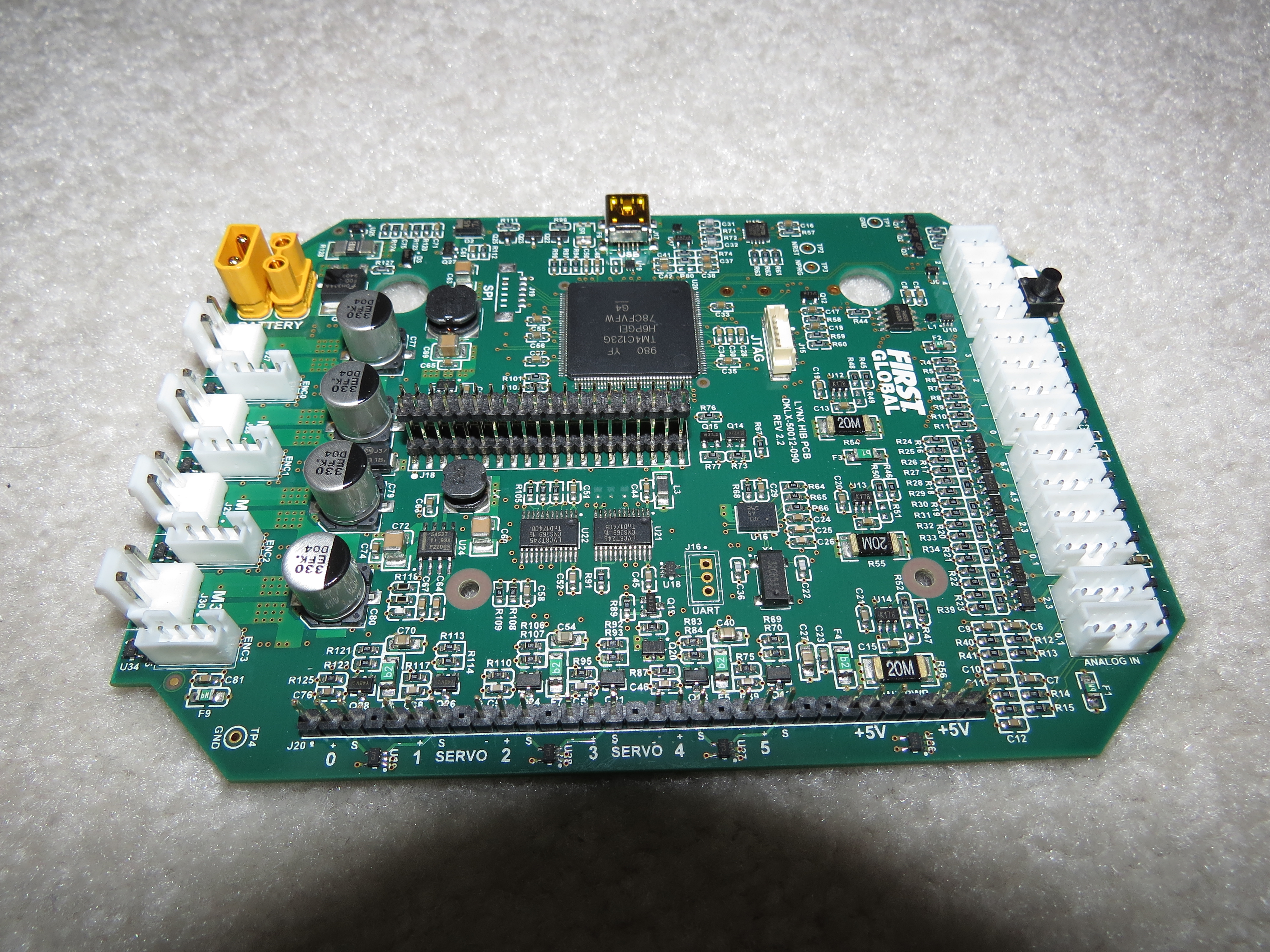
A Lynx board that was removed from its case
Processor
The microcontroller used by the Lynx board is a Texas Instruments TM4C123GH6PGE, with an Arm Cortex-M4F processor running at 80 MHZ.
Ports
The Lynx board has the following ports:
Two UART Debug Ports
The top port outputs a continuous high speed CSV stream of data from the various subsystems in the hub.
The bottom port outputs data at a baud rate of 115200 at a user specified verbosity.
Four I2C Ports
These ports are 100/400 kHz compliant.
The ports are connected to separate busses, so there is generally no need to be concerned about address collisions. However, be aware that the internal IMU shares the I2C bus with I2C port 0.
There appear to be integrated pull up resistors on this port (potentially using the built-in configurable pull-up/pull-down resistors integrated into the MCU).
Eight DIO Ports
3.3V only, current limited, can briefly supply more than the rated current spec. Pulled up internally.
Four Analog Ports
These ports are 5V compliant; you can use a level shifter to supply 5v to the sensor, but take care the analog line bypasses the level shifter. The VIN and GND lines, however, must pass through the level shifter for it to work.
Six Servo Ports
The 5V supply on the servo ports is default OFF, and will only enable once a servo is used. All six 5V pins are switched on and off together, and disabling PWM on one port will switch all of the ports off unless another servo is used.
Each pair of 2 side-by-side ports is rated for a maximum current draw of 2 amps, and the combined set of servo + 5V ports is rated for a maximum total current draw of 5 amps.
Two 5V Power Ports
The pair of 5V supply ports in rated for a maximum current draw of 2 amps, and shares the total 5 amp limit with the servo ports.
Four Motor Ports
The motor driver is a ST Microelectronics VNH5050 motor driver IC, which is capabile of handling well over the maximum amount of current an FTC motor can draw. It has integrated current sensing, and built-in thermal and current safety limits.
The output does not brake the H-bridge during the PWM off cycle. What this means is that there might be linearity issues while deaccelerating, because of momentum in the motor.
Four Encoder Ports
IMPORTANT: Only two of the encoder ports (Ports 0 and 3) can accurately track position/velocity at high speeds. There are two methods of connecting an encoder internally to the Texas Instruments microprocessor, through the Quadrature Encoder Interface (QEI) and through General-Purpose Timers (GPTs). Ports 0 and 3 use the integrated QEI and are extremely accurate at high speeds, whereas encoders using the GPTs often start to loose counts at high speeds. As a result, high Count per Revolution (CPR) encoders (those with more than around 4000 counts per revolution) expected to spin somewhat quickly (such as encoders being used in odometry pods) should NOT be used on ports 1 and 2.
Two XT30 Connectors
Care should be taken when moving around cables as these connectors have been known to fail and break off the board.
In addition, XT30s will wear and get loose with time. See XT30 Pins are Compressed - Expansion Hub Troubleshooting for details on the issue and how to fix it.
USB Mini-B Connector
Uses the FTDI FT230XQ chip to bridge the internal UART to USB, allowing an Expansion Hub to connect over USB to a Control Hub, Android device, computer, or other such device. The FT230XQ is capable of USB Full Speed (12 Mbps) on the USB side and 3 MBaud on the UART side, and 5V output to charge a phone. According to REV, the 5V output is not compatible with any of the remaining Android phones still legal in FTC. This USB chip is disabled by the compute board of the Control Hub, meaning this port is not functional out-of-the-box on a Control Hub.
Internal Connector
This connector is what is used to connect to the compute daughterboard. It has a UART connection, as well as power and ground. All Lynx modules that came is part of an Control Hub will have this connector, but Lynx modules sold as Expansion Hubs may or may not have this connector. A Lynx board from an Expansion Hub that contains the connector, when connected with a Control Hub’s daughterboard, will work as a Control Hub. To go the other way, the Hub address has to be changed to something other than the Control Hub address of 173. You can change the address once the daughterboard is removed by plugging it into an Android device running the Robot Controller app and using the function in the settings to change the address. (Note that connecting it to another Control Hub is unlikely to work, due to the address interference between the two Lynx modules. The Driver Hub works fine for this purpose, but make sure to uninstall the Robot Controller app from it afterwards, so it doesn’t potentially interfere with the Driver Station app!)
Control Hub
The Control Hub is an Expansion Hub with an embedded single-board compute daughterboard connected to it. This enables it to not need a separate Robot Controller phone, as the compute board functions as the Robot Controller. Internally, LynxCommands are sent over from the daughterboard to the Lynx board over an internal UART connection.
The compute board is based on the 96Boards CE Specification, Version 1.0, though it is unknown how many of the features of the two expansion connectors are wired up/functional beyond the UART and handful of GPIO lines used to connect to the Lynx board.
Note
The original version of the Control Hub (REV-31-1152) actually used a Dragonboard 410c as the compute board. This version of the Control Hub was never used in, nor legal for, FTC; it appears to have only been used in early FIRST® Global seasons.
The Control Hub compute board runs a customized version of Android 7.1. It does not have a proper heatsink on the SOC, only an RF shield that does not touch the SOC, which can cause thermal throttling when heavy processes such as vision pipelines are used. A large amount of heat seems to be sunk by the daughterboard PCB, which acts like a heat spreader.
SOC: Rockchip RK3328
CPU: Quad-core ARM® Cortex-A53
The device tree in the official kernel seems to indicate that the CPU can clock up to 1.5 GHz
GPU - ARM® Mali 450MP4
HDMI 2.0 support for 4k @ 60Hz
RAM: 1GB DDR3
Storage: 8 to 16GB of eMMC flash memory
“8GB eMMC 4.51” is the spec officially listed by REV, but multiple real-world units that were checked all had 16GB eMMC chips found on their boards.
According to REV, in a support email: “Original builds of the Control Hub were manufactured with 8GB eMMC chips. However, some 16GB versions were made due to supply chain constraints. Recent Control Hubs (purchased after 2022) are more likely to have the 16GB eMMC chip.”
USB: 1x USB 3.0, 1x USB 2.0, 1x internal USB 2.0 used to connect the Wi-Fi chip
Wi-Fi: Realtek RTL8821CU
IEEE 802.11a/b/g/n/ac Wi-Fi (Dual Band 2.4 & 5 GHz)
802.11w Protected Management Frames standard supported for preventing deauthentication attacks
Bluetooth 4.2 (Bluetooth 4.1 listed by REV)
Debugging UART: 3 pin header (TX left, RX middle, Ground right), 1500000 baud
Warning
Don’t take apart a Control or Expansion Hub unless you really know what you are doing. They can be damaged in the process, especially if one does not know how to properly reassemble it.
Tip
It is possible to install an Armbian Linux build from https://forum.armbian.com/topic/26978-csc-armbian-for-rk3318rk3328-tv-box-boards/ and have it work on the Control Hub. Enable the rk3318-box-led-conf3 board type using the rk3318-config command to allow Wi-FI and all USB ports to work. Enable the rk3328-uart1 overlay using armbian-config to allow communicating with the Lynx board over the internal UART connection using /dev/ttyS1.
YOU SHOULDN’T BE DOING THIS FOR FTC!
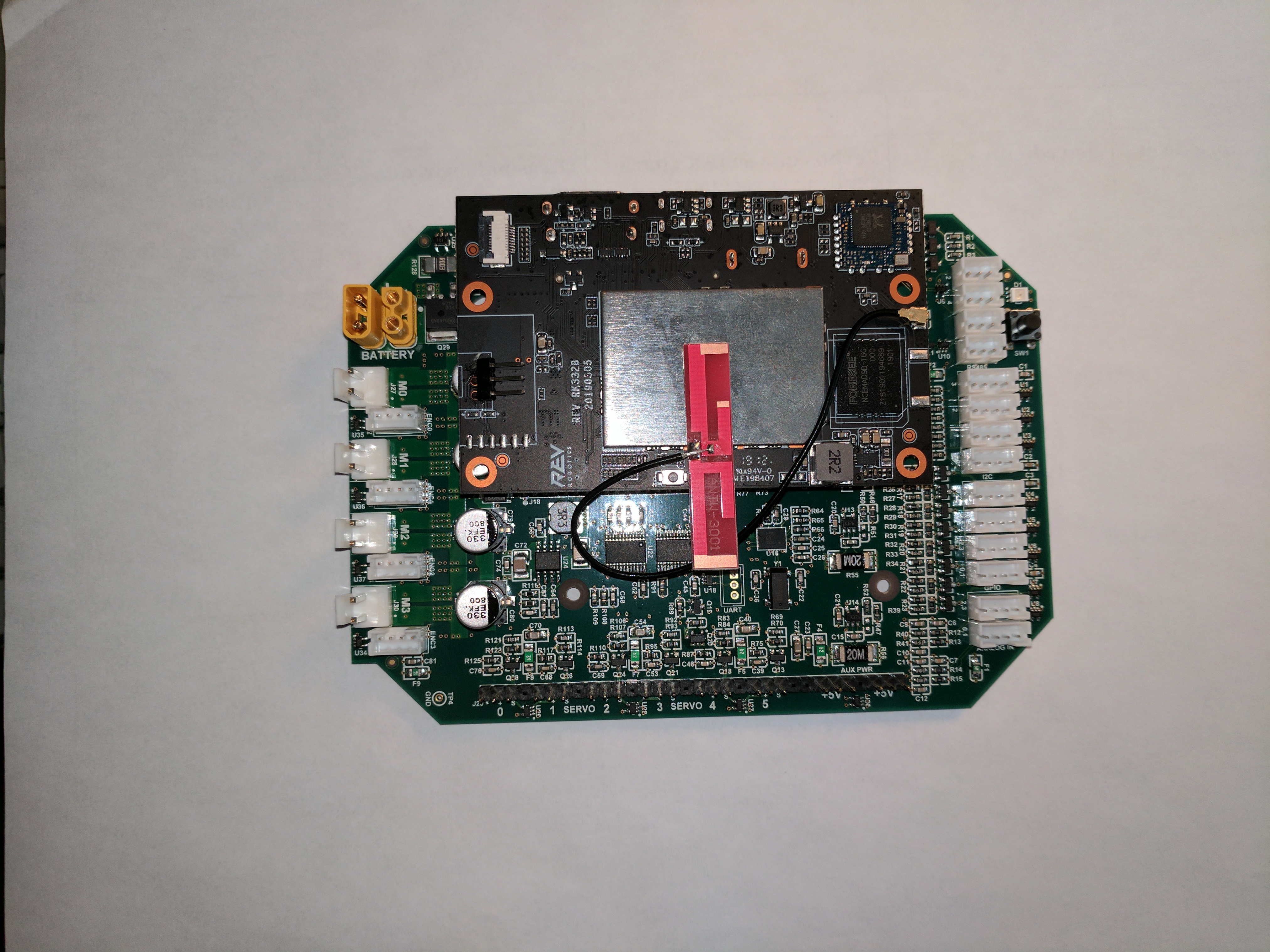
The single board computer and Lynx board from a Control Hub
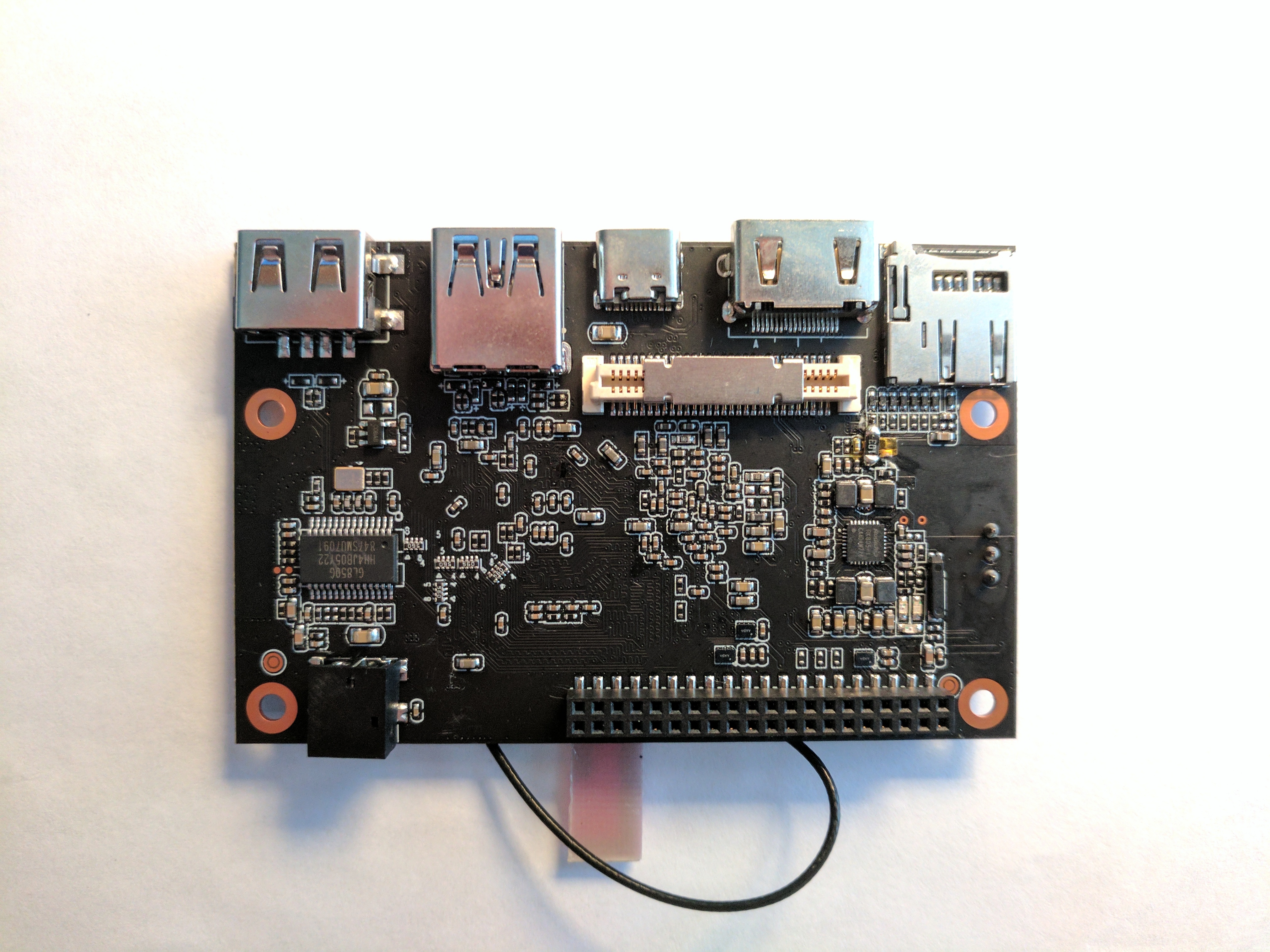
The compute board, removed from a Control Hub